
Since 2006
Welcome to CHINA SINOTRUCK(HK) LIMITED !










How to distribute a concentrated load on a 3 axle flatbed trailer
How to Distribute a Concentrated Load on a 3 Axle Flatbed Trailer
Distributing a concentrated load on a 3 Axle Flatbed Trailer takes more than placing it in the center of the deck. A heavy machine, coil or compact piece of equipment can overload individual axles or damage the trailer floor if its weight is not spread and secured correctly. This guide explains how to assess load position, use suitable load-spreading equipment and check axle limits before setting off, helping operators transport concentrated cargo more safely and confidently.
Start with the load, not the empty deck
A concentrated load puts a substantial weight through a relatively small contact area. A machine may weigh less than the trailer’s rated payload but still press too heavily on the deck through four small feet. Equally, a load that the floor can support may be positioned so far forward or backward that an axle or coupling limit is exceeded.
Before loading, establish the cargo’s actual weight, dimensions, center of gravity and contact points. Include accessories, detachable components and the weight of any steel beams, timber, cradles or other equipment that will travel with it. Ask the cargo owner for a lifting and transport drawing when the center of gravity or approved support points are not obvious.
Then check the trailer documentation for payload, axle and suspension ratings, kingpin capacity, deck loading limits and any concentrated-load restrictions. The tractor’s axle and coupling limits matter too. A maximum payload figure alone does not tell you how much weight a small section of floor can carry.
Position the center of gravity for the whole combination
The geometric center of the flatbed is not automatically the correct loading position. On a semitrailer, cargo weight is shared between the tractor through the kingpin and the trailer axle group. Moving the cargo forward generally increases the load transferred toward the tractor; moving it rearward generally increases the load on the trailer axles. The actual distribution depends on the vehicle geometry and the existing weight on each axle.
Use the cargo’s center of gravity—not merely the center of its footprint—to plan the position. Keep it as close as practical to the trailer’s longitudinal centerline, unless an engineered loading plan specifies otherwise. An offset machine can create uneven left-to-right wheel loading even when the axle-group total looks acceptable.
A useful starting estimate treats the kingpin and the trailer axle group as support points. Using their horizontal separation and the distance from the kingpin to the cargo’s center of gravity, a planner can estimate how much cargo weight each support receives. Add those estimates to the empty combination’s measured axle loads. This is a planning aid, not a substitute for a manufacturer’s load diagram or a scale check: axle spacing, suspension behavior and the tractor’s axle loads all affect the final result.
If the load cannot be positioned without exceeding a rating or a route limit, do not assume that moving it a few centimeters will solve the problem. Recalculate, reduce or divide the load where feasible, or select equipment designed for it.
Spread the weight into the trailer structure
Load spreading reduces pressure at the contact points and helps transfer weight into suitable structural members. Depending on the cargo and trailer, the solution may involve engineered steel spreader beams, a purpose-built cradle or sound timber dunnage of an appropriate size and grade. The right arrangement depends on both the machine’s support requirements and the trailer’s load-bearing design.
Place spreaders so they bear on the structural locations specified by the trailer manufacturer, rather than relying on thin deck plate alone. Check the direction, length and bearing area of each member. A long beam is not automatically effective if it bends excessively, bridges uneven surfaces or transfers most of the force through a small area at one end.
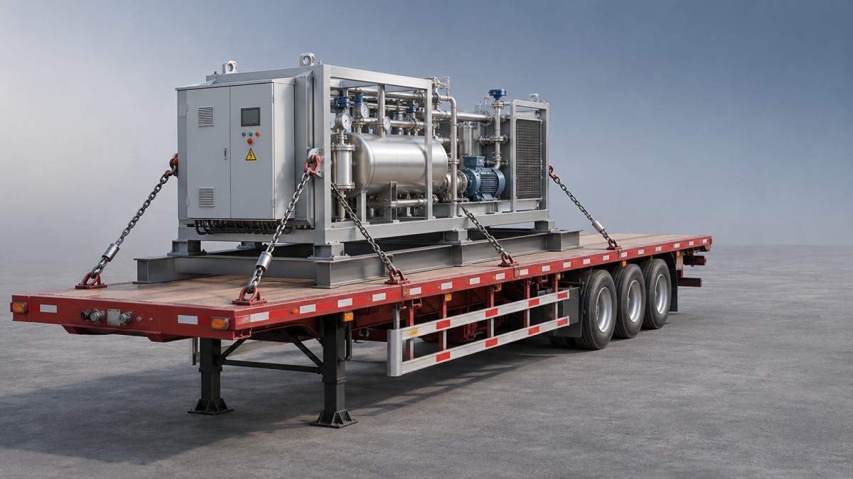
For a machine with narrow feet, the support plan should show where each foot bears on the spreaders and where the spreaders bear on the trailer. Avoid damaged, split or unstable timber, and do not stack loose pieces in a way that can shift during loading. Protect sensitive deck surfaces where necessary, but do not let padding make the support unstable.
Coils and other rolling cargo need special attention. A suitable rated or engineered cradle must support the load and restrain rolling; ordinary flat dunnage is not a substitute. Follow the cargo-specific securement requirements applicable to the journey.
Secure the cargo independently of the spreading arrangement
Spreading the load protects the deck; it does not necessarily prevent movement under braking, acceleration or cornering. Plan the restraint system around the cargo’s weight, shape and designated securing points, using chains, straps, blocking or combinations appropriate to the load and local requirements.
Check the working load limits of the tie-downs and their attachment points, including the trailer’s anchorages. A strong chain attached to an unsuitable point does not create a strong restraint system. Consider tie-down angles and the direction in which each restraint can resist movement; a device running mostly sideways, for example, may contribute little to forward restraint.
Protect straps and chains from sharp edges, and make sure blocking or cradles cannot slide with the cargo. Do not rely on friction alone unless the restraint design and applicable rules explicitly allow for it. After loading, inspect the arrangement for slack, damaged components and contact with hoses, lights or other vulnerable parts.
Weigh, inspect and adjust before the trip
Where suitable scales are available, weigh the loaded combination and check the tractor steering axle, drive axle or axle group, and trailer axle group against their applicable limits. Check individual trailer axles where the equipment or operating rules require it. Gross weight alone can conceal an overloaded axle.
If a measurement is over a limit, reposition the load only within the approved support and securement plan, then weigh again. Moving the cargo may relieve one axle while overloading another. Confirm tire condition and ratings, suspension condition, vehicle height and route restrictions as well; legal limits and permit requirements vary by jurisdiction.
During the journey, stop and inspect the load and restraints at intervals required by the operating rules and conditions. Recheck after a short initial distance if safe and appropriate, particularly when timber may settle or tie-down tension may change. Any movement, damaged dunnage or loose restraint is a reason to stop and correct the problem before continuing.
When a different trailer may be the better answer
Not every heavy shipment belongs on a standard three-axle flatbed. A compact machine may need a reinforced deck or a purpose-designed heavy-haul platform, while bulky packaged goods may call for more enclosed carrying space rather than a concentrated-load solution.
For the latter type of work, the 4-Axle Semi-Enclosed Fence Semi Trailer offers a four-axle platform and tall side panels for commercial cargo. Its stated 55,000 kg payload is a general rating, not confirmation that its floor can accept a particular machine or coil. Concentrated-load capacity, axle compliance and cargo restraint still need separate verification.
CHINA SINOTRUCK(HK) LIMITED Trailer, established in 2006, supplies several semitrailer types and provides technical support to overseas customers. For an uncertain load plan, the most useful information to take to a supplier or qualified engineer is specific: cargo weight and center of gravity, contact-point dimensions, proposed route, tractor and trailer axle data, and the intended spreader and restraint arrangement.
Related Posts
- ▶ How to Choose the Right Flatbed Semi Trailer for Your Fleet?
- ▶ Flatbed Semi Trailer: 5 Common Transportation Problems and Their Solutions
- ▶ Double Deck Car Carrier Trailer: Improve Vehicle Transport Efficiency and Reduce Costs
- ▶ What tie-down capacity does a 3 axle flatbed trailer need?
- ▶ How does axle spacing affect a 3 axle flatbed trailer's load limit?
- ▶ When is a 3 axle flatbed trailer better than a 2 axle model?
- ▶ How to distribute a concentrated load on a 3 axle flatbed trailer
- ▶ What determines the unladen weight of a 45ft skeletal trailer?
- ▶ How does a sliding axle affect 45ft skeletal trailer use?
- ▶ How to identify a worn twist lock on a 45ft skeletal trailer
CONTACT US

Established in 2006, CHINA SINOTRUCK(HK) LIMITED Trailer supplies different types of products and provides relevant technical support and services to foreign customers.
Get in Touch
*We respect your confidentiality and all information are protected.